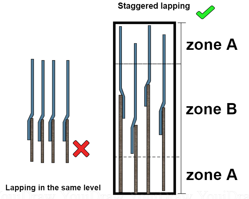
However, both codes do allow distances larger than this limit so long as the splice length is increased accordingly. In this case, there's the question of which $\phi$ to use, and I honestly don't know.
#REBAR LAP SPLICE REQUIREMENTS CODE#
The Brazilian code NBR-6118 and EC2 both put that limit at $4\phi$ or 50 mm. The codes usually define a maximum distance between lapping rebars. The arrows roughly represent the furthest distance that tension needs to travel from each bar. In the figure below, for instance, assume this is a splice section, with the tension from the large red bars being transferred to the small blue ones. However, if you are splicing multiple rebars in the same position, going from a few large diameter bars to many smaller ones, an incremement to the splice length may be required. So there's no reason to design your splice to withstand a force larger than the yield strength of the smaller bar. If the tensile force is larger (say, equal to the yield strength of the larger rebar), then the smaller rebar will rupture immediately after the splice. Therefore, if you are splicing two rebars of different diameters, the maximum tensile force that can be transferred via the splice is equal to the yield strength of the smaller rebar. However, once the splice is over, all the tension from the first rebar has been transferred to the other one, which must also be capable of withstanding that same tension. Since concrete is very weak against tension, large lap lengths are required such that the stress at any point in the concrete is not excessive. What is a splice? It is when tension force in a rebar is transferred to the concrete via adhesion and then to another rebar. Depending on the shear strength requirements, the required tie spacing may be less than that in the figure.The use of the smaller diameter is theoretically correct. The clear spacing between ties must be at least (4/3) d agg.

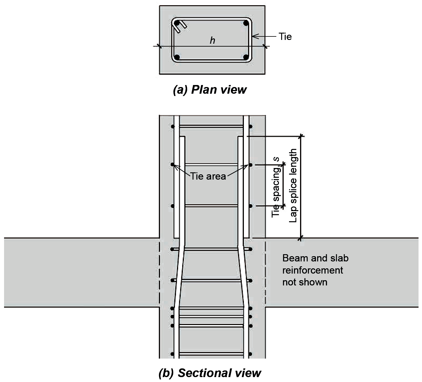
Tie spacing requirements for reinforced concrete columns in buildings assigned to SDC A and B are given in Figure 3.

Requirements for columns with tie reinforcement are given in ACI 318 Sections 10.7.6 and 25.7.2, and standard hook dimensions for ties are given in ACI Section 25.3.2. These lap splices also must be located away from the ends of the column where spalling of the concrete shell surrounding the transverse reinforcement is likely to occur due to a seismic event (ACI 318 Section 18.7.4.3). The type of lap splice that must be used depends on the stress in the longitudinal bars due to the factored load combinations (see ACI 318 Section 10.7.5.2).įor columns that are part of special moment frames in buildings assigned to SDC D, E, or F, lap splices must be tension lap splices and located within the center half of the column length. Similar tables can be created for other tie bar sizes and circular longitudinal bar arrangements.įor columns in ordinary moment frames in buildings assigned to Seismic Design Category (SDC) A or B, or in intermediate moment frames in buildings assigned to SDC C, lap splices of the longitudinal bars are permitted to occur immediately above the top of the slab, which is the preferred location for ease of construction ( Figure 2). The column face dimensions have been rounded to the nearest inch. To facilitate the selection of the longitudinal bars, Table 2 contains the minimum face dimension of rectangular tied columns with normal lap splices based on the minimum spacing requirements assuming 1.5-inch clear cover to #4 ties. Minimum face dimension (inches) of rectangular tied columns with normal lap splices.


 0 kommentar(er)
